|
General Data |
|
|
Manufacturer (OEM) |
CWT |
|
Primary Side |
|
|
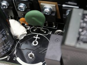
Transient Filter |
4x Y caps, 2x X caps, 2x CM chokes, 1x MOV |
|
Inrush Protection |
NTC Thermistor & Relay |
|
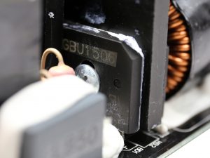
Bridge Rectifier(s) |
2x GBU1506 (600V, 15A @ 100°C) |
|
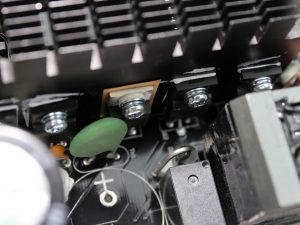
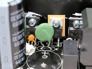
APFC MOSFETS |
2x Infineon IPA60R125C6 (650V, 19A @ 100°C, 0.125 Ohm) |
|
APFC Boost Diode |
1x CREE C3D08060A (600V, 8A @ 152°C) |
|
Hold-up Cap(s) |
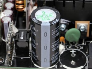
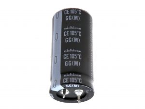
2x Nichicon (400V, 470uF each or 940uF combined, 2000h @ 105°C, GG) |
|
Main Switchers |
2x Infineon IPA60R190P6 (650V, 12.7A @ 100°C, 0.190 Ohm) |
|
APFC Controller |
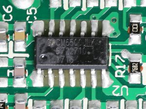
Champion CM6500UNX |
|
Switching Controller |
Champion CM6901X |
|
Fan Controller |
Microchip PIC16F1503 |
|
Topology |
Primary side: Half-Bridge & LLC Resonant Controller |
|
Secondary Side |
|
|
+12V MOSFETS |
6x International Rectifier IRFH7004TRPBF (40V, 164A @ 100°C, 1.4 mOhm) |
|
5V & 3.3V |
DC-DC Converters: 6x QM3006D (30V, 57A @ 100°C, 5.5 mOhm) |
|
Filtering Capacitors |
Electrolytics: Nippon Chemi-Con (1-5,000 @ 105°C, KZE), |
|
Supervisor IC |
|
|
Fan Model |
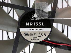
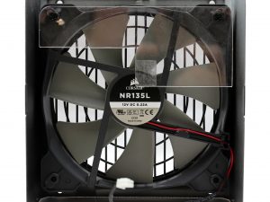
NR135L (12V, 0.22A, Rifle Bearing) |
|
5VSB Circuit |
|
|
Rectifier |
ISD04N65A (650V, 4A, 2.5Ohm) SBR, QM3004D, LS64 10L45 SBR |
|
Step-Down Converter |
|
|
Standby PWM Controller |
On-Bright OB5269CP |
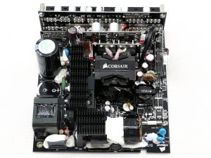
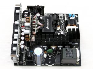
Compared to the previous generation RM850x the new has some changes. Those include a bypass relay for the NTC thermistor responsible for protection against large inrush currents. Moreover, in the primary side instead of Vishay's FETs we now find Infineon ones. Both the APFC and the LLC resonant controllers are provided by Champion. The older RMx units used Infineon controllers in those stages.
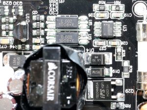
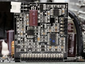
The list of changes goes on in the secondary change where the DC-DC converters utilizing six QM3006D FETs rather than a combination of four QM3004D and two QM3006D FETs. Another change here is in the fan control circuit which utilizes a micro-controller. The latter allows for a better (fine) tuning of the fan profile.
The older RM850x was based on a good platform however the new one is even better thanks to the changes mentioned above. Despite the smaller dimensions of the PCB the performance remained at the same levels and the noise output is further improved.
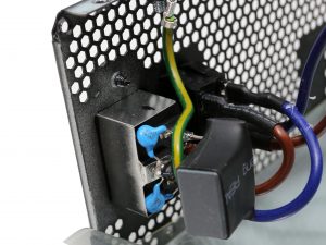
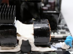
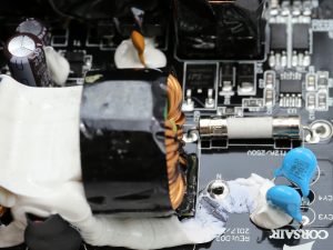
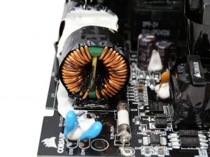
The first part of the EMI filter is on the AC receptacle including two Y and one X caps. The second part of the same filter, on the main PCB, including the same number and type of caps with the first part along with two CM chokes and an MOV.
The couple of bridge rectifiers (2x GBU1506), is able to handle up to 30A so it will easily cope with the needs of a 850W unit, even with less than 100VAC input.
The NTC thermistor, which lowers the inrush currents that occur during the PSU's start-up phase, is now supported by a bypass relay. The relay's cost is notable, however besides a small efficiency boost it also allows the fast cool down of the thermistor, so it increases the level of protection that the later provides to the unit.
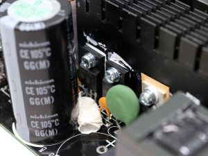
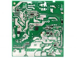
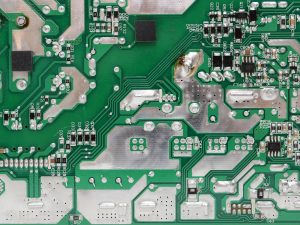
The APFC converter uses two Infineon IPA60R125C6 FETs and a CREE C3D08060A boost diode. On the solder side of the main PCB we also find a SPN5003 FET which minimizes the energy consumption while the PSU is in standby mode, by isolating the APFC converter's circuit. The bulk caps are by Nichicon (2000h @ 105°C, GG) and their combined capacity reaches 940uF, which is more than enough to offer a longer than 17ms hold-up time.
The primary switching FETs are two Infineon IPA60R190P6, arranged into a half-bridge topology. An LLC resonant converter is also used to minimize the switching energy losses.
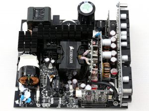
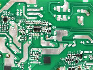
Both the APFC and LLC resonant controllers are provided by Champion and are installed at the PCB's back side. The first is a CM6500UNX and the second the famous CM6901.
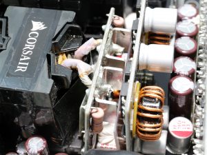
The main transformer is installed close to the board hosting the +12V FETs, in order to restrict energy losses. In some platforms the main transformer is directly soldered onto the +12V board for the same purpose.
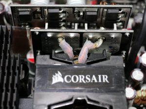
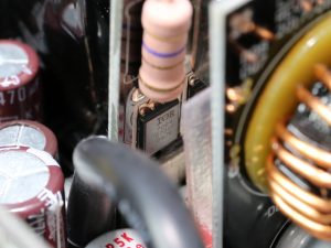
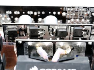
Six International Rectifier IRFH7004TRPBF FETs regulate the +12V rail. They are cooled by a number of small bus bars.
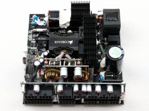
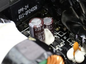
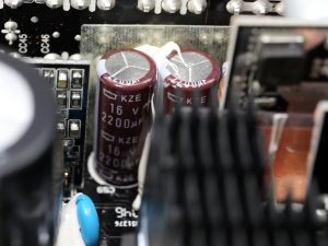
The electrolytic filtering caps are provided by Chemi-Con and belong to its mainstream KZE and the higher-end KY lines. A number of polymer FPCAPs caps is also used, for the +12V and the minor rails.
The voltage regulation modules that generate the minor rails consist of six QM3006D FETs. The common PWM controller is a ANPEC APW7159.
The 5VSB circuit uses an increased number of components: a ISD04N65A SBR, a QM3004D FET, a 10L45 SBR and a AME5268 step-down converter. The standby PWM controller is a On-Bright OB5269CP.
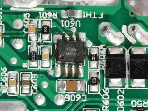
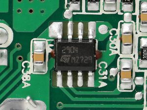
The supervisor IC is a Weltrend WT7502 which is supported by a LM393G dual differential comparator.
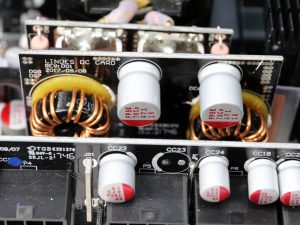
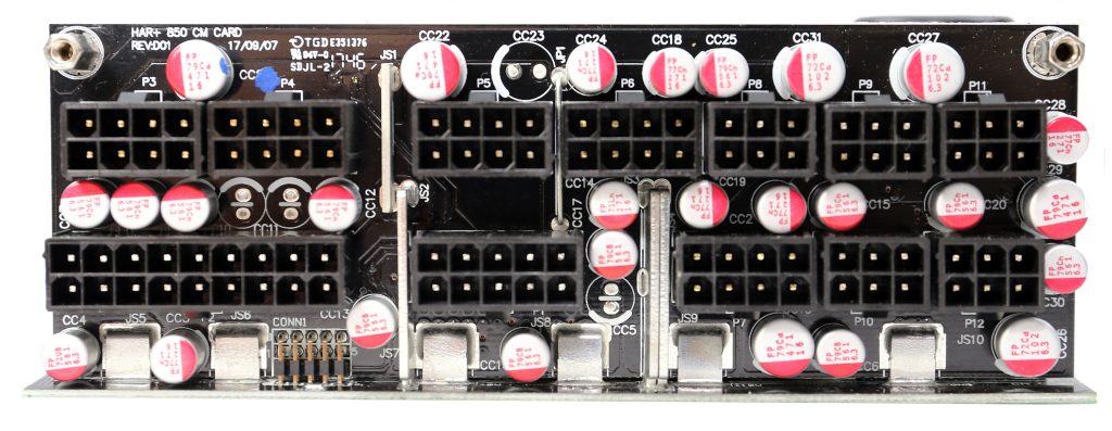
At the front side of the modular board a large number of polymer FPCAPs provides an extra ripple suppression layer.
The soldering quality is good, with proper solder joints. On top of that we didn't spot any super long component leads. The only problem here is the lead-free solder, which unfortunately is mandatory for any product sold in the EU (and not only).
This type of solder is of the worst kind to work with, demanding much higher temperatures which can damage sensitive components, and besides that it can go bad after some time. It can also easier break/crack than the solder containing lead. Because of the increased RMA rates due to the lead-free soldering, its initial purpose for a cleaner environment goes south.
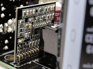
The fan controller is a Microchip PIC16F1503 and the rifle-bearing NR135L fan is also used in the new RMx units. There was no reason to change the fan after all, since it does a great job and it is reliable enough to outlive the ten-year warranty period.
 KitGuru KitGuru.net – Tech News | Hardware News | Hardware Reviews | IOS | Mobile | Gaming | Graphics Cards


