| General Data | |
| Manufacturer (OEM) | FSP |
| Platform Model | Raider |
| Primary Side | |
| Transient Filter | 4x Y caps, 2x X caps, 2x CM & 1 DM chokes, 1x GTD |
| Inrush Protection | NTC Thermistor |
| Bridge Rectifier(s) |
1x
|
| APFC MOSFETS |
2x Infineon IPA60R190P6 (650V, 12.7A @ 100°C, 0.19Ω)
|
| APFC Boost Diode |
1x STMicroelectronics STTH8R06FP (600V, 8A @ 130°C)
|
| Hold-up Cap(s) |
1x Teapo (420V, 390uF, 2000h @ 85°C, LH)
|
| Main Switch |
1x STMicroelectronics STF25N80K5 (800V, 12.3A @ 100°C, 0.26Ω)
|
| Reset Switch |
1x CET CEF03N8 (800V, 2A @ 100°C, 4.8Ω)
|
| Combo APFC/PWM Controller |
FSP 6600 IC
|
| Topology |
Primary side: Active Clamp Reset Forward
Secondary side: Synchronous Rectification & DC-DC converters |
| Secondary Side | |
| +12V MOSFETS | 2x |
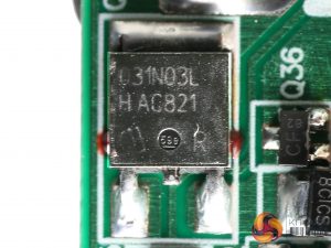
| 5V & 3.3V | DC-DC Converters: 4x Infineon IPD031N03L G (30V, 90A @ 100°C, 3.1mΩ) PWM Controller: 2x FSP6601 |
| Filtering Capacitors | Electrolytics: 8x Teapo SC (1-3,000 @ 105°C, SC), 4x Teapo SY (3-6,000 @ 105°C) Polymers: 5x CapXon (modular board), 1x Teapo (-12V board) |
| Supervisor IC | Weltrend WT7527 (OVP, UVP, OCP, SCP, PG) |
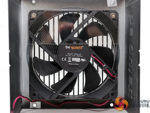
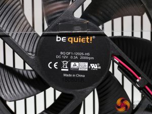
| Fan Model | BQ QF1-12025-HS (120mm, 12V, 0.30A, 2000 RPM, Rifle Bearing) |
| 5VSB Circuit | |
| Rectifier FET |
CET CEF02N7G (700V, 1.3A @ 100°C, 6.75Ω)
|
| Rectifier SBR | 1x PS30U60CTR |
| -12V Circuit | |
| Rectifier IC |
7912
|
This is FSP's Raider platform, which is more budget than performance oriented. At the primary side it uses an Active Clamp Reset Forward (ACRF) topology which offers high efficiency without needing extra components such as an LLC resonant converter.
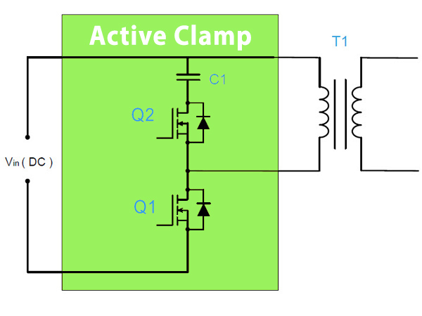
In low capacity ACRF platforms a couple of FETs are used with one of them being the main switcher (Q1), while the other one is the reset switch (Q2) which disconnects the clamp capacitor when Q1 is active.
The power is transferred from the primary to the secondary side only when the Q2 FET is active. This topology allows for an almost lossless switching of the Q1 FET, since while it is off the drain voltage is very low.
The second major advantage of the ACRF topology is the long hold-up time that it provides, even with low capacity bulk caps. Since those caps are among the most expensive parts of a power supply, the savings are notable.
The scheme below shows an ACRF design. When Q1 is active voltage runs through the T1 transformer, so there is power transfer from the primary side to the secondary one. When the Q2 FET is active, clamp voltage is applied to T1.
As C1's capacity increases, the ripple voltage gets lower however a high capacity C1 affects the transient response, so a good engineer has to find the optimal balance between ripple and performance under transient loads.
The major breakthrough in the Pure Power line was made last year since the Pure Power 10 models were equipped with DC-DC converters, for the generation of the minor rails. The previous units used a group-regulation scheme which tied the +12V and 5V rails together, with only the 3.3V rail being independently regulated.
Finally, from the Pure Power 10 line FSP started (finally) to use NTC thermistors to restrict the large inrush currents that occur during the start-up phase.
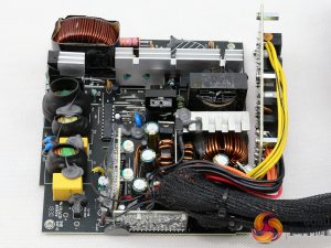
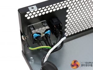
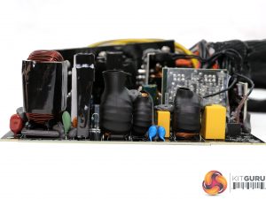
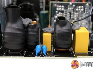
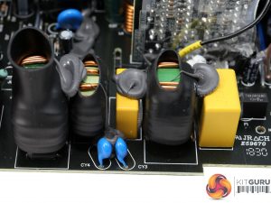
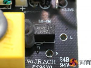
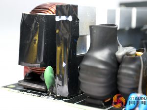
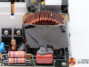
The first part of the EMI filter consists of two Y and one X caps. The second part, on the main PCB, includes the same amount of Y and X caps, two CM chokes, a single DM choke and a Gas Discharge Tube (GDT) instead of an MOV.
We would prefer to see the latter component being used, since it has faster response and good overall clamping performance. The only problem with MOVs is that repeated surges cause wear and while clamping the voltage rises along with surge current.
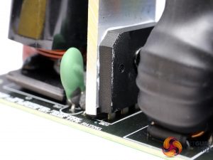
The single bridge rectifier is bolted onto a dedicated heatsink. We cannot make out its model number without desoldering it, something that we want to avoid since those parts are very sensitive to high temperatures.
Next to the bridge's heatsink is a small NTC thermistor, responsible for protection against large inrush currents. Unfortunately FSP didn't use a bypass relay, to restrict energy losses and allow for the thermistor's fast cool down.
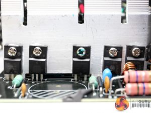
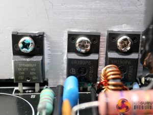
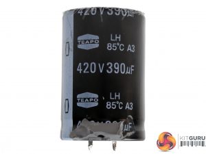
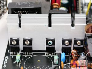
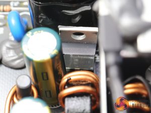
The APFC converter uses two Infineon IPA60R190P6 FETs and a single STMicroelectronics STTH8R06FP boost diode. The bulk cap is provided by Teapo and is only rated at 85°C. A better component should be used in this stage.
Although this cap has low capacity, still thanks to the ACRF topology the hold-up time that it provides is long.
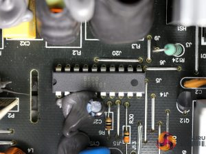
The combo PFC/PWM controller is an FSP6600 IC. There is no information available about it, since it is exclusively made for FSP products.
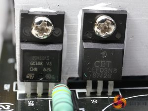
The main switching FET is a STMicroelectronics STF25N80K5 and the reset switch is a CET CEF03N8.
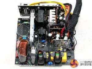
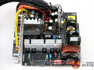
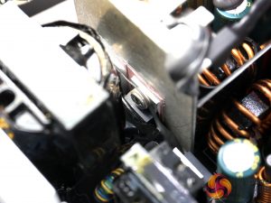
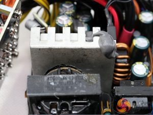
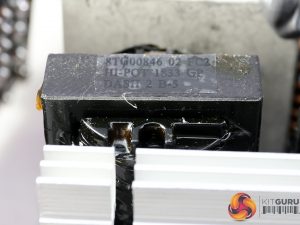
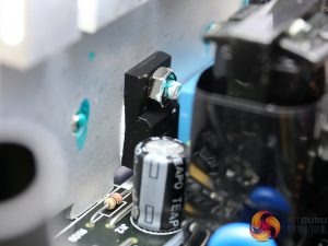
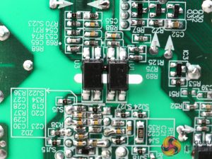
Two FETs regulate the +12V rail, and it is impossible to identify them without removing either their heatsink, or the main transformer. In general this platform is hard to work with.
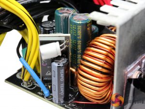
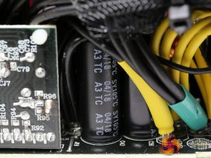
All filtering caps are provided by Teapo with the majority of them belonging to the mainstream SC line. We were expecting to see higher quality parts in a product of this price range.
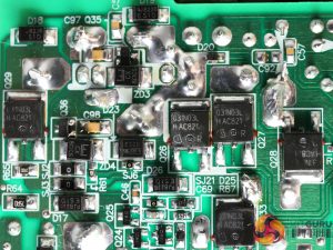
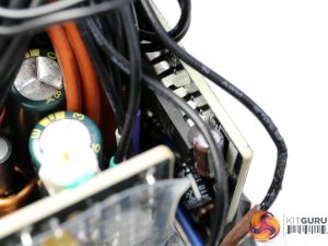
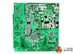
The voltage regulation modules are installed on the solder side of the PCB, instead of a daughter-board. In total four Infineon IPD031N03L G are used in this circuit, while the PWM controllers are two FSP6601 ICs.
The 5VSB rail is rectified by a CET CEF02N7G and a PS30U60CTR SBR.
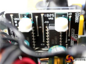
The supervisor IC is a Weltrend WT7527 which among others has two +12V OCP channels.
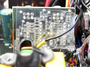
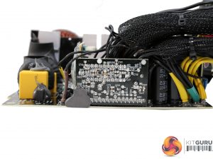
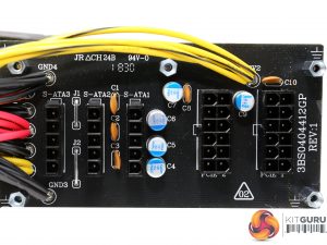
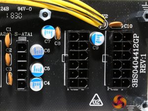
At the front of the modular board several polymer CapXons are installed, along with five ceramic disc caps which are used for high frequency ripple suppression.
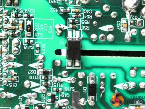
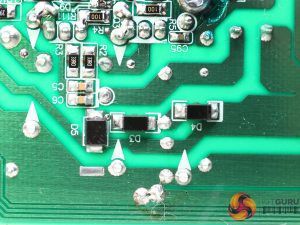
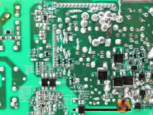
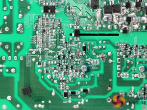
The soldering quality is not the best we have seen from FSP. Moreover, some component leads are quite long. On the positive side, the PCB is clean, without any notable traces of flux residue.
The couple of burn marks are our fault, since we had to desolder some parts and because of the lead-free solder, high temperatures needed to be applied.
The cooling fan (BQ QF1-12025-HS) uses a rifle bearing and measures 120mm in diameter. Thanks to the relaxed fan profile, the noise output remains low and on top of that, we didn't notice any high-pitched sounds (aka coil whine) coming out from this platform.
 KitGuru KitGuru.net – Tech News | Hardware News | Hardware Reviews | IOS | Mobile | Gaming | Graphics Cards


