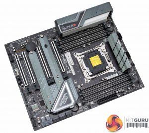
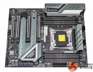
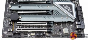
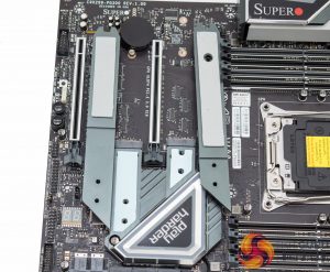
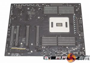
The design of the SuperO C9X299-PG300 is quite neutral and should suffice for most prospective buyers. The colour scheme is a mix of a number of shades of grey all on top of a matte black PCB. The only design flair that stands out as potentially polarising is the “Play Harder” slogan printed on a heatsink sticker. For the fussy customer with some patience, and a heat gun, this can likely be removed.
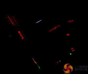
The onboard LED lighting covers three zones – the chipset/PCH heatsink, the isolated audio PCB and the rear I/O shroud, with two optional 12 volt (pin1) GRB (pin 2,3,4) headers available too. All of this is controlled by the SuperO Booster software which contains the lighting options.
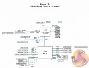
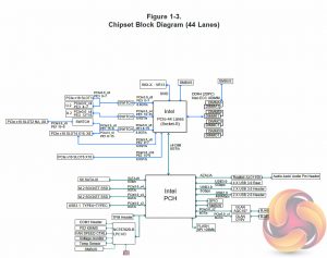
The PCIe lane configuration depends on the CPU used – 28-lane CPUs naturally have more limitations than 44-lane CPUs. The provided block diagrams give a clear indication on what PCIe bandwidth is shared between which slots and ports.
SATA storage provision is a little low for Intel's X299, six ports is less than the default eight ports provide. However, Supermicro attempts to make up for this with dual U.2 and dual M.2, all operating at up to PCIe 3.0 X4 32Gbps when lanes are available.
Since X299 provides 8 SATA channels by default, it seems like a missed opportunity that Supermicro has not used the unused pair of SATA channels to offer both M.2 slots in SATA mode as well as PCIe.
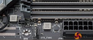
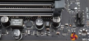
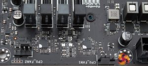
Fan provision is a little on the low side too for a motherboard of this calibre – just three fan headers dotted around the board for system fans and two for the CPU cooler.
USB header connectivity is equally average with just two internal headers for USB 2.0 and USB 3.0 (USB 3.1 Gen 1) available.
Onboard diagnostic options are excellent with a code reader, power and reset buttons and a clear CMOS button.
The audio solution uses an isolated PCB along with an unshielded Realtek ALC1220 codec. The capacitors are 105 degrees Celsius rated ELNA audio capacitors and there are no additional amplifiers fitted beyond what the ALC1220 codec already provides.
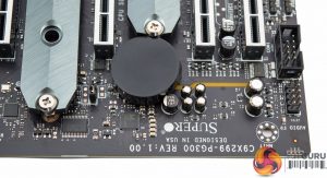
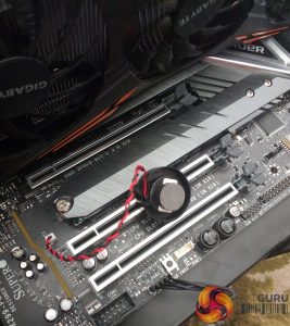
The black plastic circle holds the CMOS battery and connects via a two pin cable, sometimes this pops out of place and is on the fiddly side to replace back.
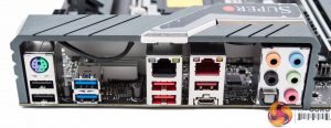
The rear I/O provides the following ports:
- 1 x PS/2 Keyboard/Mouse combo port
- 2 x USB 2.0 (black)
- 2 x USB 3.0 (blue)
- 2 x USB 3.0 (red)
- 1 x USB 3.1 Type-A (Red)
- 1 x USB 3.1 Type-C
- 1 x Intel Gigabit LAN RJ45
- 1 x Aquantia 10 Gigabit LAN RJ45
- 5 x Audio Jacks
- 1 x Optical S/PDIF
It's worth reiterating our earlier caution that this rear I/O does not have four USB 3.1 ports, it has 2. Some of the Supermicro literature, both online and in paper form, suggested four USB 3.1 ports. This board has a single ASM3142 controller that provides a maximum of two USB 3.1 ports, one of those is translated into Type-C by an ASM1543 controller.
There is a diagram on page 11 of the user's manual that gives the correct illustration of the USB setup.
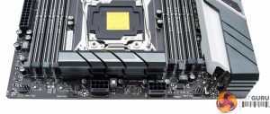
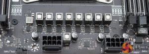
The CPU socket uses two 8 pin EPS connections and has immediate access to a pair of fan headers.
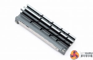
The M.2 provision is excellent in that both ports support PCIe 3.0 x4 32Gbps and have cooling solutions. The M.2 slot nearest the CPU socket supports up to 22110 devices (110mm) while the other slot is limited to 2280 (80mm).
Under the motherboard there isn't a great deal to see aside from a strip of 12 LEDs underneath the isolated audio PCB. All the screws and fastenings used underneath are easily removed with a cross-head screwdriver.
The CPU VRM is a true 8-phase solution with 1 inductor and 1 dual-MOSFET (high- and low-side in a single chip) per phase. The dual-MOSFET packages are International Rectifier TDA21470 which are high-end units capable of a peak of 225 amps at 94% efficiency according to the data sheet.
The maximum rated average current for the TDA21470 is 70-amps which means this power solution can easily handle 70-90 watts per phase (560-720-watts total) while maintaining 94~95% efficiency.
The CPU heatsink isn't large but does have a decent weight to it and a good number of fins. Given the MOSFETs it cools are very efficient it should be up to the job.
At a power draw of 300-watts for the VCore, 37.5-watts (1.8V x 20.83A) per phase, the system would be about 94% efficient and generate about 18-watts of heat.
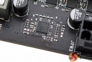
The PWM controller for the CPU is marked Infineon “XDPE11280A” but there's no data sheet provided for this controller online. However, it is a fully digital multi-phase controller according to a number of online chip resellers and being an Infineon unit its definitely high-quality and probably expensive.
There are at least a further four Primarion “PXE1110CDM” digital PWM controllers dotted around the memory and CPU area, likely responsible for the memory, VCCSA and VCCIO VRMs. Interestingly, Apple chooses to use these PWM controllers in the iMac Pro so the expectation is that these are also high quality controllers.
There are a number of smaller Infineon TD21240 power stages, six or more, located near the Primarion PWM controllers.
These TD21240 power stages are rated for a maximum average current of 40amps with a typical efficiency between 91 to 94% according to the data sheet. These are less powerful than the TDA21470 units used to supply the CPU, rated for 40A versus 70A, but given these do considerably less work they are highly over-engineered for the job.
 KitGuru KitGuru.net – Tech News | Hardware News | Hardware Reviews | IOS | Mobile | Gaming | Graphics Cards


