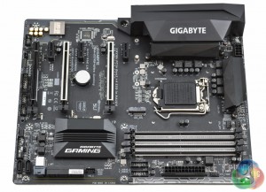
For a low-cost offering the overall design and styling for the Gigabyte Z270X-Ultra Gaming is pleasant and effective in its purpose to appeal to a wide audience. Motherboard vendors seem to adhere to the same wider market trends of which the latest seems to be a neutral colour scheme with RGB lighting.
Gigabyte have opted for a two-tone black and grey which is enhanced by some silver shielding on the memory slots and CPU-derived PCIe 16X slots. RGB lighting is multi-zone and found in a number of locations on this particular motherboard:
- Between the memory lanes
- On a strip adjacent to the 24 pin connector
- On a strip underneath the motherboard adjacent to the SATA ports
- Underneath each of the two shielded PCIe lanes
- Under the CPU VRM heatsinks
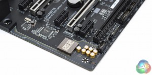
- Along the Isolated audio PCB
- (optional) 12v G R B W LED header located by the last PCIe 16X slot
Down the side of the motherboard you will find a pair of USB 3.0 headers, a Thunderbolt add-in card connector, six SATA III ports, two SATA Express, one U.2, the motherboard 24 pin and a system fan header. Due to there being LED lighting down almost the entire length of the motherboard most connections are offset and recessed into the motherboard to make room for the LEDs.
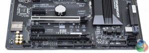
Along the bottom of the motherboard are the front panel connections, two front panel USB connections (up to 4 ports), a fan header designated for a system fan or pump, a TPM header, the 12v G R B W LED header and front panel audio.
The fact Gigabyte have designated this SYS_FAN3 fan header for the pump is strange since both other system fan header ports are closer to the CPU socket where the pump is most likely to be located.
The audio section consists of a fully shielded Realtek ALC 1220 codec on an isolated PCB surrounded by seven Nippon audio capacitors.
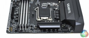
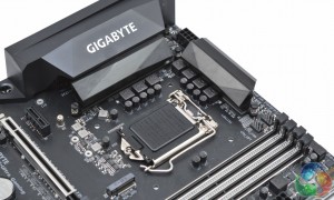
The CPU socket draws power from an 8 pin EPS connection and a 7 phase VRM, with another phase for the DRAM. The number of phases is a little on the low side for the segmentation of this motherboard but will still suffice for most overclocking scenarios. Any motherboards higher than this in Gigabyte's product stack for Z270 will need to equip more phases.
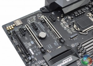
There are three fan headers near the CPU socket, 2 CPU and 1 SYS. The single M.2 socket for this motherboard is located right below the CPU socket so users of large air heatsinks will likely need to install the M.2 drive prior to the CPU cooler.
The PCIe lane configuration is virtually identical the ASUS Maximus IX Formula with the same lane spacing and electrical configuration. It's a decent configuration as it gives the flexibility to run multi-GPU setups and large air coolers won't be blocked by the first PCIe lane since it is only a X1.
Most users will likely not need additional expansion cards for networking or audio since the onboard solutions are fairly strong already, but Gigabyte does sell an optional Thunderbolt add-in card that would work with this board should the user desire.
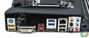
The rear I/O seems a bit sparse and could benefit from more USB ports. There are four USB headers to provide front USB ports but few cases have more than 2 USB header cables coming from the front panel. Gigabyte would do well to turn one or two of those headers into additional USB ports on the rear I/O.
That said many AIO liquid CPU coolers, fan controllers and front panel bay devices (e.g. card readers) can still make use of these internal USB headers.
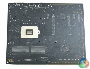
Underneath the motherboard it's possible to get a glimpse at the assembly method for the main heatsinks and shroud. The PCH heatsink is easily removable by Philips head screw, so too is the I/O shroud, but the CPU VRMs use a fiddly push-pin system.
The LED strip on the underside of the motherboard is visible from this view, it's formed from 5 individual LEDs. The electrical configuration of the PCIe lanes can be validated from the bottom and it is: 1X, 16X, 1X, 8X, 1X, 4X.
 KitGuru KitGuru.net – Tech News | Hardware News | Hardware Reviews | IOS | Mobile | Gaming | Graphics Cards



I think I’m over with all these hardwares. The customer service is rubbish left, right, up and down, vendors and manufacture alike, MSI, Samsung the list goes on… I lost a M.2 screw, and MSI’s support could care less.
Hello Ryan
I’ve just bought this board for my new build. Do you think there’s a way to make the auto voltage function less aggressive?
Thanks 🙂
Hey, you could apply a core voltage offset. I discussed it at the bottom of the UEFI page. I found that -0.1 was enough to keep power down and was still perfectly stable. You may be able to get a lower voltage yourself (-0.1 to -0.2) depending on your CPUs capability. You could also choose a lower LLC setting instead of the Auto LLC setting. The core voltage offset is under MIT-CPU Core Voltage Control, if you leave the core voltage as auto then do the dynamic vcore option (use + and – on the keyboard to get down to -0.1, it’s a bit fiddly). MIT-Advanced Power Options has the LLC setting. Medium or lower should keep the voltage a bit less aggressive but the offset will be the most effective way.
Gigabyte may well alter the voltage behaviour with BIOS updates too so keep an eye out! Also be sure to have the “balanced” windows power profile to get adequate clocking/voltage down for less intensive tasks.
Alright, thanks for the tips!
I’ll make sure to look out for future updates.
The correct screw size is 2.0 x 3mm (CM2x3-3.3)
should be available at hardware / electronics stores.
Thanks for the suggestion, I’ve gone to two electronics stores specialising in screws, nuts and bolts, none of them has anything remotely as small as the M.2 screws. Hope, some manufacturers in computers parts will make them for sale in the future.
Isn’t that audio test pretty seriously flawed? If you do loop back the results are only as good as the line in ADC is and doesn’t really tell anything about the line out DAC quality. Judging by Realtek ALC1220 specs it has much worse line in than line out quality.
Can i run my I7 6700K on this Board?
yes
I see the F4 Bios has ‘V-Core Voltage Adjust’ has anyone used this and did it correct the high auto voltage issue?
Really? This board gets a 8 / 10 when by the picture it looks like it has a craptacular 7 phases? Combine that with the UEFI layout issues, bad auto voltages and thats plenty to bring it down to a 7 / 10.
Stop kissing Gigabytes arse and rate things accordingly.
eu preciso aprender a configurar a memoria g.skil 3200mhz nessa placa. alguem pode me ajudar?
does this motherboard support NVME?
its about what’s said in the reviews, not about the ratings themselves.
the Written Reviews tell you a lot more then just some arbitrary subjective-rating.
an 8/10, 7/10 and even a 6/10 could have a lot different meanings and interpretations base on the person. Some people may not view a 8/10 not that highly while a 6/10 might be seen as a ‘good’ score, to some.
It’s all based on the person perception of the numbers. You can’t objectively score a product like a video-game for example.
That’s why its important to read the ACTUAL review, rather then just look at the Rating/awards given to it. To see what is actually said about the product and make an informed decision based on that, rather then trying to make a decision based off an arbitrary rating.
Fallout New Vegas for example got a 84 on metacritic, though in my opinion its one of best games of that year, even now in my opinion it still holds up quite well as a great game. That said, it got an 84 out of 100 for a score. Does Scoring really matter? It’s meant to give a generic-overall view of the game in simple terms. like “Great Game” or “Great Product”.
7/10, 10/10, 1/10, etc doesn’t matter. What matters is the content of the review, what they say about the product itself, how it runs, it feels, how it looks, features, how it compares to other products in its industry, etc. Don’t take the 8/10 to heart, too much just because you feel the score should be different. Numbers mean different things to different people, so an 8 is not always the “8” the way you may be perceiving it.
Yes, but will depend on how many PCIE lanes you are using and your CPU.
If i enter a value of 1-1.299 it will work and when i put 1.35 for example it switches the mode to AUTO and locks at 1.3
On page 10 of the first guide he specifies how he has a profile with 1.35 voltage and on the second link there are screenshots of him at 1.375
https://view.joomag.com/gigabyte-z270-overclocking-guide-gigabyte-200-series-overclocking-guide/0767815001483933769
http://www.kitguru.net/components/motherboard/ryan-martin/gigabyte-z270x-ultra-gaming-motherboard-review/4/
Is it because I am on version f6 of the BIOS or is my mobo simply locked @ 1.3?
In the first guide he also mentioned how he set his CPU Vcore Loadline Calibration to TURBO and I don’t have this setting available
Z270P-D3 + i7-7700k BIOS version f6