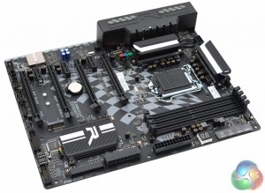
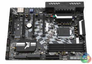
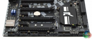
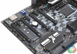
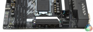
Biostar's Racing Z170 GT7 is no show-stopper in terms of its looks but it still fits the bill for a gaming motherboard with its quirky racing theme.
The black, white and grey colour scheme is neutral which helps this motherboard be versatile for a number of different colour schemes. This is especially true when you take into consideration the extensive RGB lighting options available with it.
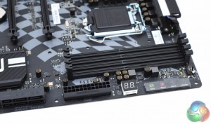
One of the more unique features of the Biostar Racing Z170 GT7 is the inclusion of touch buttons, which Biostar calls “GT TOUCH”. There are four of them – power, reset, sport and eco, with the latter two being power & performance profiles similar to, for example, the ASUS EPU and TPU profiles and switches. Biostar also provides a debug code reader and LN2 mode switch in this area of the motherboard.
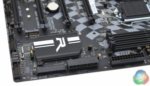
Down near the chipset heatsink, which has a “carbon fibre style” wrap, you'll find all six SATA ports are incorporated into SATA Express ports.
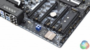
The base of the motherboard hosts the other connectivity – some system fan headers, USB 2.0 and 3.0 headers, two BIOS chips and the BIOS selector switch.
PCIe lanes are plentiful but cannot all be populated at the same time as there are bandwidth sharing caveats. In total there are four physical 16X slots and three 1X slots and maximum possible bandwidth per slot is 16X, 1X, 4X, 1X, 8X, 1X, 4X in top to bottom order (CPU socket to edge of motherboard).
The bandwidth caveats are that are that when both PCIe X16 (4X electrical) slots are populated two of the PCIe 1X slots will be deactivated.
The audio hardware, which includes two sense amplifiers and electrolytic audio capacitors, is hosted on an isolated PCB and the Realtek ALC898 codec sits beneath a shield to reduce electronic interference.
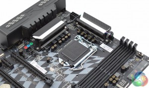
The motherboard uses a 6+2+1 phase VRM for the CPU socket, iGPU and DRAM, respectively, paired to Ferrite chokes and solid caps.
The CPU draws power through a single 8pin EPS connection while the CPU fan headers are actually below the CPU socket near the first PCIe lane, rather than near the CPU power. The 5050 RGB header is actually located next to the CPU fan headers mid-board, rather than with the USB headers at the lower end of the motherboard which could make cable management troublesome.
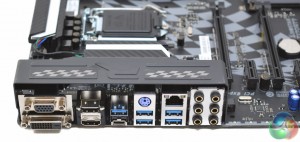
The rear I/O area has a metal cover decorated with the Biostar Racing-themed chequered flags. The rear I/O has the following connections:
- 1 x PS/2
- 1 x USB 3.1 Type-C Port
- 5 x USB 3.0 Port
- 2 x HDMI Connector
- 1 x DVI-D Connector
- 1 x VGA Port
- 6 x Audio Connector
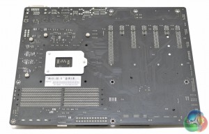
Underneath the motherboard is a clearer view at the electrical wiring of the PCIe lanes. It's also possible to see that only the CPU heatsinks are screwed into place, users looking to remove or alter the chipset heatsink will have to tread carefully with the pushpin system.
 KitGuru KitGuru.net – Tech News | Hardware News | Hardware Reviews | IOS | Mobile | Gaming | Graphics Cards


