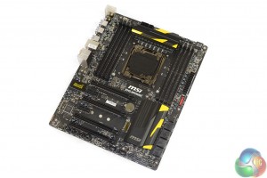
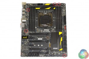
Layout-wise, MSI’s X99S MPower is almost identical to the company’s X99S Gaming 7. The key differences come from switching some of the latter’s gaming-orientated features for ones with overclocking intentions on the MPower.
The board’s standard ATX PCB is entirely black, with all three of the heatsinks featuring subtle yellow hints to create an eye-catching contrast. MSI’s Lightning range of graphics cards are, arguably, the perfect companion for the company’s OC series boards when it comes to colour coordination.
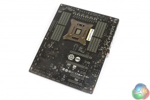
Looking at the rear of the PCB outlines the physical PCIe lane allocation. I am surprised to see MSI omitting a strip heatsink behind the CPU MOSFETs for cooling the six power phase doublers.
A sizable backplate withstands the stress created by a large, hanging CPU cooler.
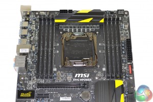
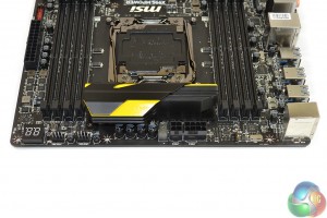
A good amount of clearance is maintained around most of the LGA 2011-3 socket. This will be beneficial to hardened overclockers who plan to use large LN2 or DICE pots.
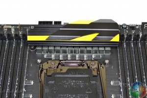
That same clearance feedback does not hold true when referencing the VRM heatsink above the socket. Wide CPU cooling equipment could see interference problems caused, although the solid metal block is low-profile enough to minimise incompatibility.
Up to 64GB (the manual states 128GB, but good luck finding 16GB non-ECC DIMMs right now) of DDR4 memory is supported, with a quoted maximum operating frequency of 3333MHz, via overclocking. MSI’s current UEFI versions support a 3200MHz multiplier (32x 100MHz, so higher if the BCLK is increased from 100MHz) and we have seen screenshots of G.Skill sticks working at 3340MHz.
A twelve phase power delivery system is employed to feed a Haswell-E CPU. Twelve Solid Ferrite Chokes (SFC) are joined by a further dozen Fairchild FDMF5823DC MOSEFTs. The Fairchild MOSFETs, which are rated to handle a current of 55A with an operating temperature of up to 150°C, show similarities to International Rectifiers’ respected IR355x solutions.
Intersil’s ‘hybrid’ ISL6388 6-phase PWM controller operates the 12-phase CPU power delivery system with assistance from six rear-mounted phase channel doublers marked ‘617C FMRN’.
Two Powervation PV3203 controllers manage memory system power operations. The memory’s physical power delivery system seems to consist of four (plus one supplementary) MOSFETs marked ‘NTMFS4C05N’ and a further two marked ‘NTMFS4C08N’ per DIMM bank (two sets in total). This is in addition to two 470 microFarad and two 330 microFarad capacitors, as well as two R22 and one ‘tR47’ choke(s) per DIMM bank.
Aluminium-core ‘Dark’ and low-profile ‘Hi-c’ capacitors also form part of MSI's Military Class 4 power delivery system.
Two 4-pin fan headers are found along the motherboard’s top edge, one of which is allocated CPU duties, with the other running from the system fan channel. The other 4-pin CPU fan header is found between the DIMM bank and rear IO shield.
Next to the fan headers is a convenient two-digit debug LED, which overclocking users will be very happy to see. When Windows is loaded, the current CPU temperature is displayed.
MSI adds an additional 4-pin CPU power connector to bolster the current input from the 8-pin EPS port. Haswell-E CPUs can draw high levels of current when overclocked heavily.
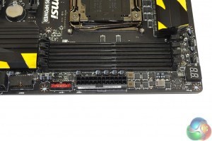
An outwards-facing USB 3.0 header sits adjacent to the 24-pin power port. The USB 3 header operates from the X99 chipset.
This top-right corner is the position where I would have liked to see the voltage (V-check) points placed.
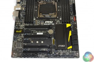
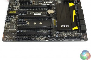
A continuing trend is the similarity between MSI's X99S MPower and Gaming 7. That same trend holds true for the expansion slot arrangement.
Up to 3-way SLI/CrossFire is supported when using either 28-lane (5820K) or 40-lane (5930K, 5960X) processors. 4-way configurations with sufficient bandwidth are not possible (as also suggested by the slot spacing), although I do not see this as an issue for a sub-£190 motherboard.
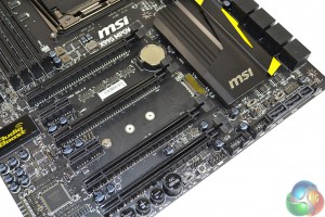
As with the Gaming 7, the MPower's PCIe connections for a 40-lane CPU are allocated as (from top to bottom full-length PCIe slots): x16 for a single card, x16/x16 for two cards, and x16/x16/x0/x8 for three cards. The one- and two-card configurations support PCIe 3.0 x4 for the M.2 connector, but three graphics cards will drop that link to PCIe 2.0 x2. That’s a big bandwidth hit on the storage front; we would have preferred MSI to drop one of the three cards to x8 link speed and maintain the PCIe 3.0 x4 connection for a high-speed M.2 drive.
Using a 28-lane chip, a single card runs at x16, but two operate via sixteen and eight PCIe 3.0 links, respectively, and three cards all get eight PCIe lanes each. PCIe 3.0 x4 for the M.2 connector is preserved throughout.
And as was the case for the Gaming 7, PCIe bandwidth optimisation is equally unclear in the MPower's manual.
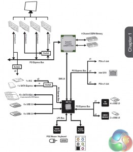
That third full-length PCIe slot that shares sixteen lanes with the first connector can, despite MSI’s advice, be used with a 40-lane chip. Sticking graphics cards in the first, second, and third full-length slots should, in theory, result in an x8/x16/x8 + PCIe 3.0 x4 configuration. MSI’s documentation doesn’t highlight it, but we see no reason as to why that wouldn’t be supported (as backed up by the above block diagram).
Expansion slot layout is decent, but could be better. I would have preferred MSI to use the first and third full-length PCIe slots for two x16 graphics cards, rather than the first and second. Back-to-back dual-slot boards always present a cooling headache. And that's without considering the potential bandwidth reduction when using triple-slot cards that are popular amongst overclockers.
3-way SLI or CrossFire with a 40-lane CPU sees a potential cooling gap left between the second and third cards (assuming dual-slot coolers), but this also makes the SATA Express connection impossible to use due to its large connector and bad positioning.
The usual front panel audio, USB 2.0, and chassis headers are found along the MPower's bottom edge. Just below the chipset heatsink are the dual BIOS and slow mode switches.
Coined Easy Button 3 by MSI, the set of onboard buttons can be particularly useful to overclockers who are running the board on a bench setup. Accessing them in a chassis environment is fairly simple too, provided you don't have a graphics board forcing button blockage.
As already pointed out, the 10Gbps SATA Express connector is going to be rendered inaccessible as soon as a long graphics cards is installed in either of the lower two PCIe slots. MSI should have changed its orientation or positioning to avoid such inconveniences.
MSI implements a ‘Turbo M.2′ connector that runs off four PCIe 3.0 lanes from the CPU to provide up to 32Gbps of data transfer speed. Taking its lanes from the CPU means that an M.2 device can be used at the same time as a SATA Express drive. If all of the CPU’s PCIe 3.0 lanes are being used by expansion cards, the M.2 connector can steal the SATA Express port’s two chipset-fed PCIe 2.0 lanes to provide a 10Gbps connection.
M.2 SATA devices are also supported in the slot, although this renders SATA ports 5-6 (and the SATA Express connector) unusable.
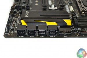
Eight right-angled SATA 6Gbps ports all operate from the X99 chipset. The remaining two connections are bundled together to help form the SATA Express port.
Placing one of the USB 3.0 headers in a right-angled orientation is one of my favourite moves for a motherboard vendor to make. Hiding the cumbersome front panel USB 3.0 cable is a far simpler task when it doesn’t stick vertically out of the board.
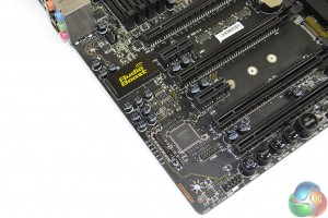
Audio Boost mark 1 is used on the X99S MPower. One of the subtle differences between this system and the version 2 used on many of MSI's Gaming boards is the exclusion of the power-boosting header.
Based around the Realtek ALC1150 and its 115 dB Signal-to-Noise Ratio (SNR), MSI’s Audio Boost system also calls upon a pair of Texas Instruments’ OPA1652 amplifiers. We know that the TI OPA1652 is perceived as a particularly potent operational amplifier, capable of driving high – up to 600 Ohm – impedance headphones.
The sceptics may say this is needless hardware causing price inflation, but there will also be users who value the system's addition for periods when they aren't overclocking.
MSI's onboard V-Check Point Lite positions are found in the board's bottom-left corner. This is a bad position because it makes the points almost impossible to access in a chassis or multi-GPU environment. Placing them near the 24-pin connector in the board's top-right corner would have been far superior.
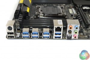
Eight blue-coloured USB 3.0 ports are supplied through a combination of sources. Although it is not listed in MSI’s manual which ports operate from which controllers, our empirical testing gives an insight into where the connections derive. Two ports beneath the LAN connector operate from Intel’s X99 chipset. The two directly to the left of those are provided by ASMedia’s PCIe 2.0 x2-fed ASM1042AE host controller. The remaining four operate from a PCIe x1 VIA VL805 host chipset.
It is important to know how the ports are fed their bandwidth because, as our testing will show, there are noticeable speed differences between each of the USB 3.0 host controllers.
Intel's I210-AT Gigabit NIC is used, as well as a further two USB 2.0 ports and a PS/2 connector. I like the inclusion of USB 2.0 ports because USB 3.0 connectors (especially from third party chipsets) can still cause some issues with Windows installations and other low-level activity.
The clear CMOS button is well-placed to make access simple. It conveniently features a blue LED which is handy for users shuffling around the rear of their case in search of the button.
Five 4-pin fan headers are handled by Nuvoton’s excellent NCT6792D+ Super IO chip. The reason we like Nuvoton’s chip so much is because, using a Z97 motherboard with onboard voltage reading points, we have tested its voltage readings to be highly accurate when compared to the levels read from a multimeter.
Distribution of the five fan headers is good. Three fan headers around the CPU area is good for users with dual-fan AIO coolers. I would have liked to see a header placed near the 24-pin connector to cater for users with multiple front chassis fans.
 KitGuru KitGuru.net – Tech News | Hardware News | Hardware Reviews | IOS | Mobile | Gaming | Graphics Cards



So there’s a new bios out soon that handles high speed ram better then eh? Interesting as I’m running this mobo with 16GB of 3GHz Hyper X Predator ram and currently stuck running it @ 2666 so would be nice if theres a new bios out soon which’ll help take it to full speed…
As for those worried with tight dual GPU placement, I’m running SLI and have the cards in slots 1 & 3 instead with 2 empty, lots of room for cooling that way and works absolutely fine!