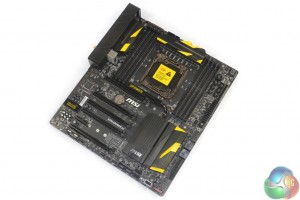
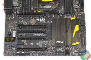
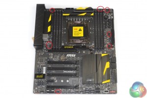
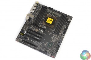
MSI outfits the X99A XPOWER AC in a bold yellow and black colour scheme that is typical of the company’s OC series motherboards. Splashes of yellow on the heatsinks provide eye-catching contrast to the dark black PCB.
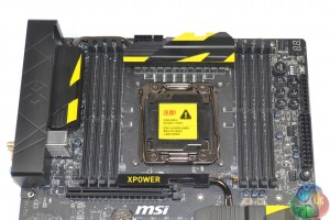
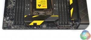
Up to 128GB of DDR4 memory can be installed in the eight single-latch DIMM slots. MSI states support for memory frequencies of up to 3333MHz in a quad channel configuration.
Spacing around the CPU socket should keep LN2-enthused overclockers happy. The surrounding area is devoid of any high-rise capacitors or notable interference points making it relatively straightforward to insulate for use with sub-zero cooling.
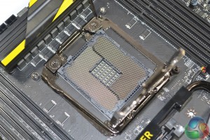
MSI also strips away a large proportion of the CPU socket bracket in order to further reduce interference for sub-zero users. Only the basic cooler mounting holes remain, although they can be switched out for MSI’s included bolt-through CPU cooler bracket.
MSI makes use of added pins in the CPU socket (like Asus pioneered with its OC Socket design) in order to unlock greater flexibility for voltages and operating frequencies. Cache frequencies and voltages are the main area where the added pins show greatest benefit.
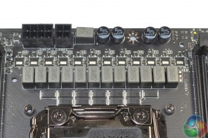
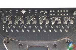
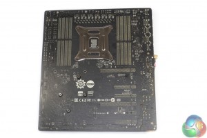
MSI uses a twelve-phase power delivery system to feed the hungry LGA 2011-3 CPUs, although the configuration is not a true twelve-phase design. Intersil’s ISL6388 PWM controller is a six-phase design that requires teaming with six of Intersil’s ISL6617 phase doublers to drive the twelve physical phases. The doublers are mounted on the board’s rear side, without a cooling strip.
Twelve Fairchild FDMF5823DC (marked DF05AB 5823DC) smart power stage modules are used for the MOSFET-style solution. The modules integrate a driver IC, Schottky diode, high- and low-side MOSFETs, and thermal monitor into a single package that is rated to handle a 55A current.
When being used in an extreme overclocking environment, an integrated power module solution may have the benefits of lower path lengths between the electronics components. Twelve Super Ferrite Chokes (SFC) assist the MOSFET modules and are likely to be rated for a 55A or 60A output given the MOSFETs’ current handling capabilities.
Nestled above the MOSFET heatsink are 8-pin and 4-pin CPU power connectors. The use of both connectors is probably wise on an overclocking-geared X99 motherboard due the Haswell-E CPUs’ high current draw capabilities.
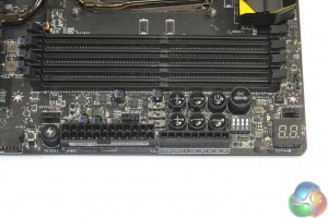
The power delivery system for memory seems to be identical to that on MSI’s X99S MPower motherboard. Aluminium-core ‘Dark’ and low-profile ‘Hi-c’ capacitors also form part of MSI’s Military Class 4 power delivery system.
A total of three Powervation PV3203 controllers manage memory, system, and chipset power operations. The memory’s physical power delivery system seems to consist of a total of two (plus one supplementary) Fairchild MOSFETs marked ‘DE45AE 22CF 070D’ (possibly related to the FDMS3660S dual N-channel MOSFETs) per DIMM bank (two sets, four MOSFETs in total for DRAM). This is in addition to two 470 microFarad, as well as two R22 and one ‘tR47’ choke(s) per DIMM bank.
MSI places the board’s overclocking buttons, LED debug display, and motherboard switches in the bard-s top-right area, near the DIMM slots. While this location has its drawbacks when sub-zero memory pots are being used (the buttons are likely to freeze or get blocked), it does seem to be favoured by many overclocking enthusiasts.
The Slow Mode switch is a particularly convenient tool for users who are trying to break world records (the system slows down in order to maintain stability while the benchmark is not running). I can also see the use of MSI’s ‘lightning bolt’ complete discharge button for when a truly buggy overclock is causing misfiring POST attempts.
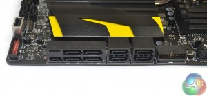
All ten (two are along the bottom edge) of the SATA 6Gbps ports are provided by the X99 chipset. Two of the ports combine to form the 10Gbps SATA-Express connector.
A right-angled USB 3.0 header is great for cable management cleanliness although it does require extra chassis width. That extra width is fine when using an ATX board, although it does become a difficulty even with large cases due to the X99A XPOWER AC board’s EATX form factor.
An outwards-facing header may have actually been preferable in this situation.
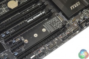
MSI provides the Turbo M.2 connector with up to 32Gbps of bandwidth by means of four PCIe 3.0 lanes from the CPU. This is excellent for providing support to some of the market’s fastest M.2 devices, such as Samsung’s SM951.
The M.2 slot also supports SATA operation and PCIe 2.0 x2 using two lanes from the X99 chipset (stealing them from the SATA-Express connector).
MSI’s X99A XPOWER AC provides support for 4-card SLI and CrossFire.
With a 40-lane CPU, up to four cards can run in 4-way SLI or CrossFire with a trio of x8 connections and one x16 link. Using the four-lane M.2 connection steals lanes from the graphics card slots, although we imagine that 4-way SLI users (extreme benchmarkers) are unlikely to be interested by faster storage when their tests are CPU- and GPU-intensive.
A 28-lane CPU drops SLI support to 3-card, although 4-way CrossFire is still usable thanks to its functionality with four PCIe lanes. Three cards can be used alongside a PCIe 3.0 x4 M.2 device, providing a high-end graphics subsystem that can be used in tandem with high-speed storage.
Slot spacing is excellent. This is an extreme overclocking board so it is likely to spend most of its time with a number of graphics cards installed. But for times when only the CPU is being pushed, or perhaps the board is being used for gaming downtime, spacing of the PCIe expansion slots provides plenty of cooling capacity.
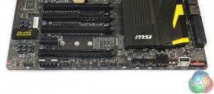
The standard affair of front panel connectors is found along the motherboard’s bottom edge.
MSI installs two SATA 6Gbps connectors in an outwards-facing orientation on the bottom edge. This may have the purposes of easier access for overclockers who have the ETAX motherboard mounted on their test bench.
There’s also a second USB 3.0 header, an outwards-facing USB port that is convenient when using the board on a test bench, the dual BIOS switch, and a molex connector to provide extra power to heavy GPU configurations.
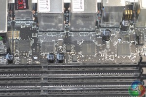
MSI’s Audio Boost system is based around the Realtek ALC 1150 audio codec. Accompanying the widely-used codec is a pair of Texas Instruments OPA1652 op-amps and Nichicon capacitors.
A segregated PCB path with yellow LED and EMI shielding for the codec are used to minimise signal interference.
The all-important clear CMOS button features a blue LED to make it easier to find in the dark or around the back of a chassis.
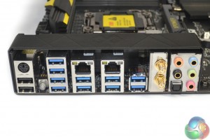
Two USB 3.1 Type-A ports are provided by the ASMedia ASM1142 PCIe 2.0 x2 chipset. MSI could do a better job of distinguishing these ports by colouring them a different shade of blue, as Asus and ASRock have done.
A stack of USB 3.0 ports are provided by expanding a pair of single USB 3.0 connections from the X99 chipset and expanding them into four ports each.
Antenna connections for the Intel Wireless-AC 7260 802.11ac WiFi card stick out on the rear IO section. MSI also includes dual Intel Gigabit NICs (I218V and I210AT) although I’m not quite sure of the relevance of these on an extreme overclocking motherboard.
Positioning of the X99A XPOWER AC’s seven fan headers is excellent. Six headers are within reach of the CPU socket, with the final serving general purposes along the motherboard’s bottom edge. This configuration is smart for an overclocking motherboard because the bottom-edge fan headers may be used to power a GPU-cooling fan, while the rest of the headers cluster around the motherboard’s business area.
Monitoring and control functionalities are handled by the Nuvoton NCT6792D+ chipset.
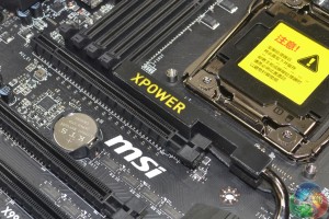
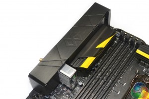
Aesthetic touches are provided in the form of a yellow LED placed beneath the XPOWER heatsink that illuminates the text. There is also the rear IO cover.
The bare 8-layer PCB shows plenty of potential for use with a full-cover waterblock. There is plenty of space around the chipset area to mount a large waterblock compartment and a clear run is set from the MOSFETs down to the chipset.
That is not to say that a water block manufacturer will release a block, however.
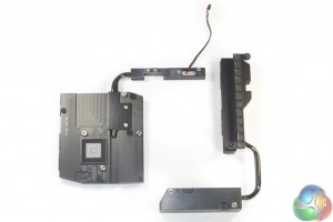
Removing the heatsinks is a simple task, which is good news for cooling aficionados.
The sizeable MOSFET heatsink is connected via heatpipe to a block of metal that increases the cooler’s effective surface area.
 KitGuru KitGuru.net – Tech News | Hardware News | Hardware Reviews | IOS | Mobile | Gaming | Graphics Cards




Your first choice kitguru