

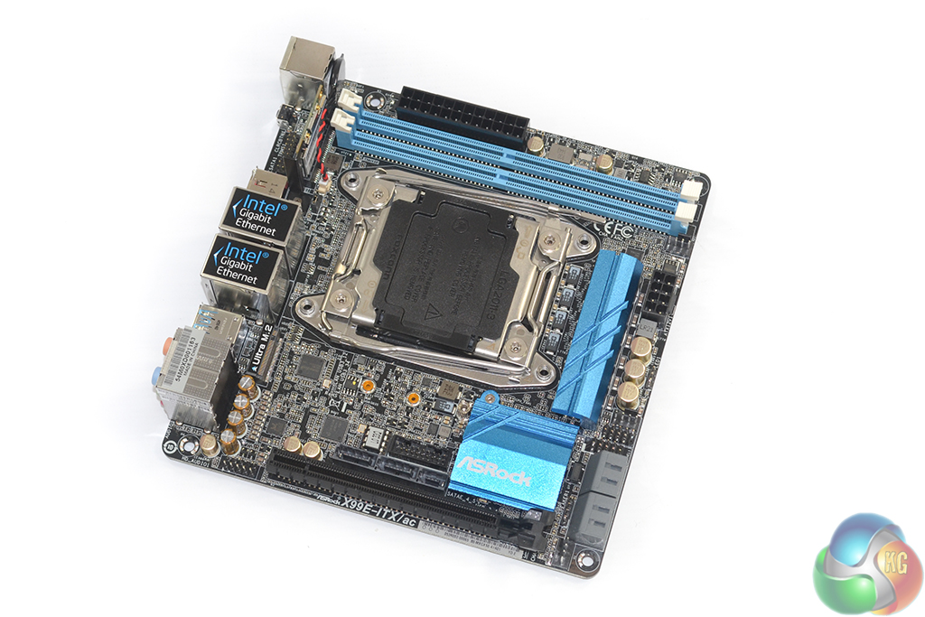
Central to the ASRock X99E-ITX/ac mini-ITX motherboard is its gargantuan Intel LGA 2011-3 CPU socket. Despite ASRock's uses of narrow ILM mounting holes, the CPU socket still spans a large proportion of the motherboard's total surface area.
Just like its bigger brothers, ASRock outfits its mITX offering with a light blue and black colour scheme. Both heatsinks and the DIMM slots offer a light blue contrast to the dark PCB and remaining ports.
A six-phase power delivery system feeds the LGA 2011-3 CPU socket. ASRock offers support for both consumer – Core i7 – and professional – Xeon E5 v3 – processors that use the LGA 2011-3 socket. That gives users the opportunity to install a Xeon processor with up to 18 cores for a powerful portable workstation, or the venerable eight-core 5960X for market-leading consumer performance.
Given the compatibility with Xeon and Core i7 chips, it is no surprise that the motherboard also supports non-ECC (consumer) and ECC (professional) memory. Up to 32GB of DDR4 RAM can be installed in the board and frequency support is provided for over 3200MHz data rates, with the aid of overclocking (using non-ECC, consumer memory).
It is worth pointing out that ASRock does not implement any hardware or software limitations on overclocking. Provided your CPU supports overclocking (i.e. not a Xeon), the X99E-ITX/ac provides access to all of the trademark overclocking options that you would expect to see on a full-sized ATX motherboard.
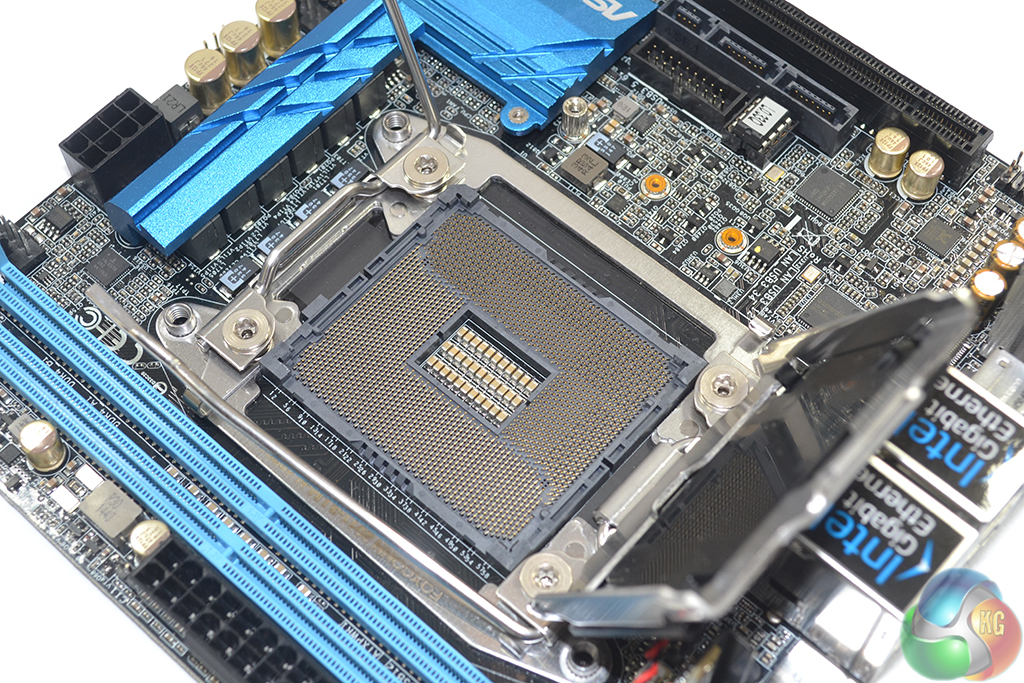
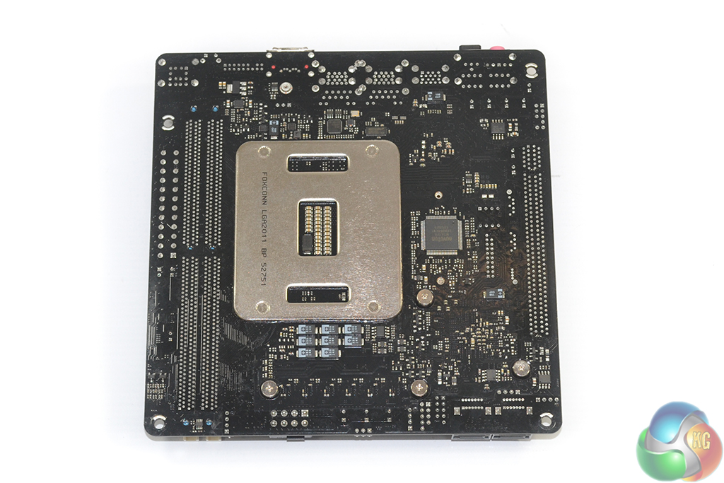
The X99E-ITX/ac is ASRock's first motherboard to use the company's ‘X Series OC Socket' implementation. This is effectively ASRock's way of catching up with Asus' OC Socket design that uses additional pins (in the region of 2083) to provide greater overclocking capacity, rather than the standard 2011. Asus' OC Socket motherboards have shown that the additional pins are particularly useful for opening up higher CPU cache frequencies.
On the power delivery side of the board, an Intersil ISL6379 controller manages the six-phase VRM. Six Fairchild FDMF5821DC 60A driver MOSFETs (marked DE28AD 5821DC) are used for power switching. The units are more of an integrated solution than a simple MOSFET – that is, they integrate the high- and low-side MOSFETs, the driver IC and Schottky diode, and a thermal monitor onto the single package. This solution, which shows similarities to International Rectifiers' IR355x packages, helps ASRock save valuable PCB space.
Six 60A chokes and a mixture of flat-caps and Nichicon 12K Platinum-rated capacitors complete the main components of the CPU power delivery system. It wouldn't be too much of a sweeping statement to say that the design is essentially that used on ASRock's 12-phase boards chopped in half. Using ASRock's same calculations, the system may be good for up to 650W, although 400-450W (6 x 60A x 1.3V – losses) seems a far more reasonable estimation, assuming one can cool such a thermal load.
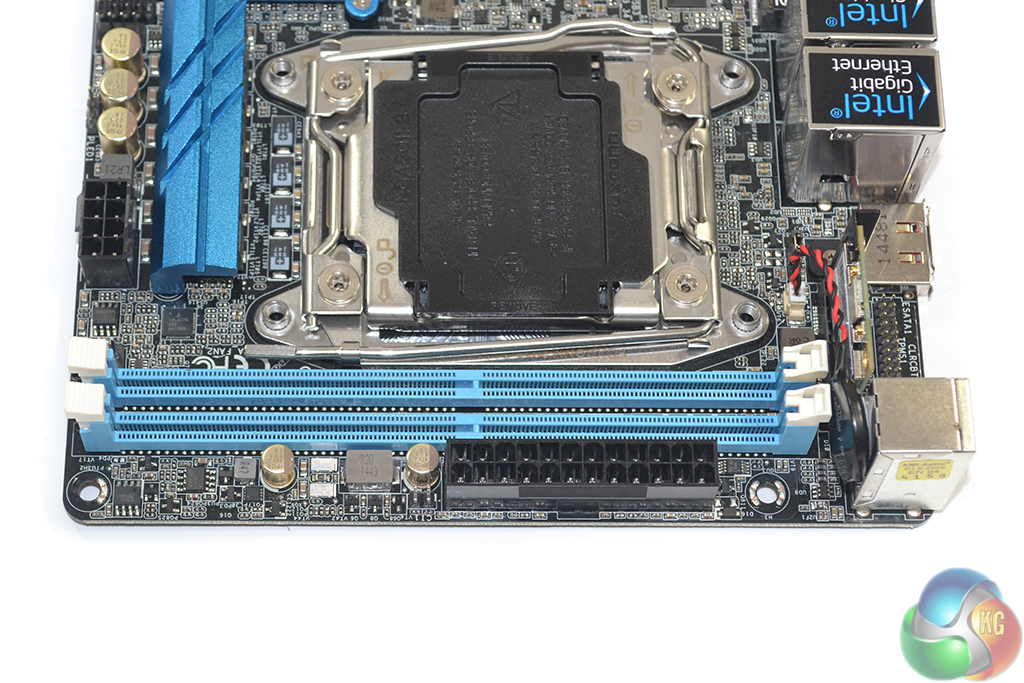
ASRock positions the 24-pin power connector along the motherboard's upper edge. While this may seem like an illogical move, truly compact mini-ITX cases do not follow the same motherboard-upright convention that typical ATX alternatives do. That said, it did take a lot of effort and a 24-pin extension cable to manage neat routing in the Phanteks Enthoo Evolv ITX chassis.
There is very little room between the pair of single-latch DDR4 DIMM slots and the CPU socket. I would recommend installing memory before mounting an overhanging CPU cooler.
And on the topic of DIMM slots, the X99E-ITX/ac motherboard's pair is a noticeable step down from X99's typical four or eight. Using full-sized DIMMs, ASRock was simply unable to fit four locations on the mITX PCB. As our test results will show, however, stepping down to dual-channel memory may not offer as much of a performance hit as one may have assumed.
Until we see widespread availability of SO-DIMM DDR4 modules on the consumer market, two DIMM slots is about as good as it gets for mITX X99 motherboards.
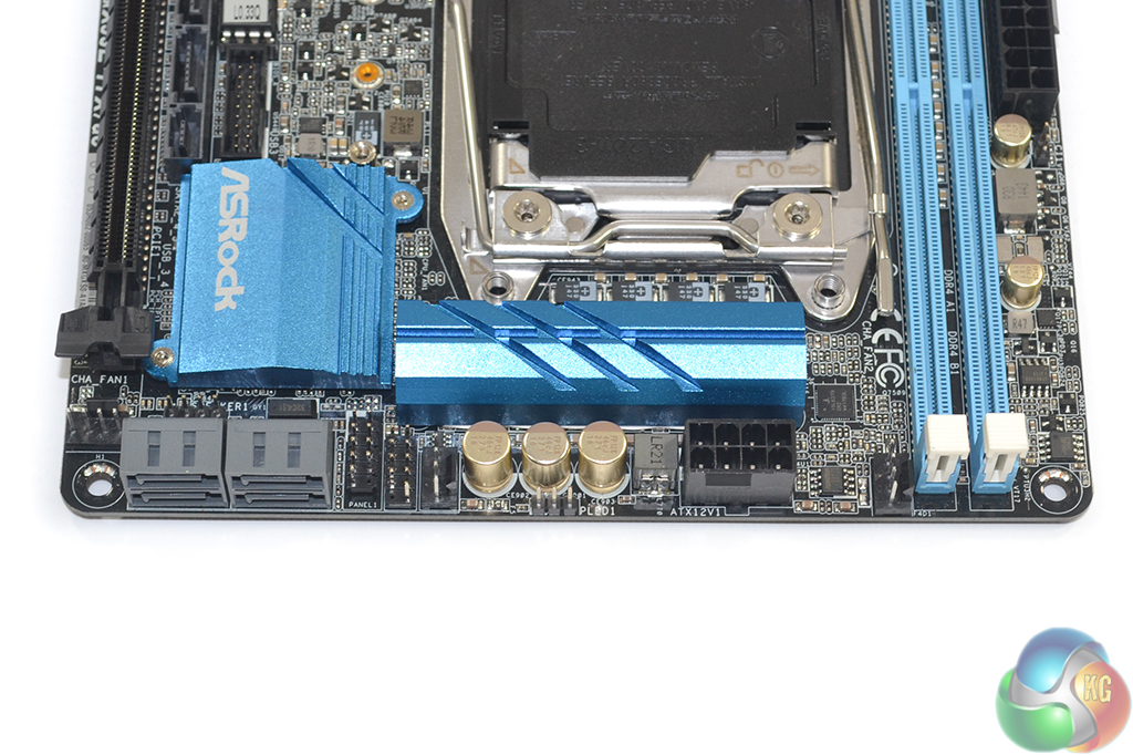
Along the motherboard's right-side are the 8-pin CPU power connector, all three 4-pin fan headers, the USB 2.0 and front panel headers, and four SATA 6Gbps ports. The right-angled orientation of the SATA ports may cause problems for some users with miniature cases; however they do make cable management more aesthetically pleasing in a vertical mITX chassis.
ASRock uses a small heatsink to cool the MOSFETs and another low-profile block of metal to remove heat from the chipset. Both heatsinks are separated, however I would have liked to see them connected via a heatpipe in order to give the MOSFET cooler a great effective surface area in the low airflow, mITX environment. This could have then led to a low profile fan being installed on the chipset heatsink to further enhance heat transfer away from the loaded MOSFETs.
While some readers may gasp at the sight of somebody contemplating the addition of a small chipset fan, that typically brings an annoying whine with it, the LGA 2011-3 CPUs genuinely stress a motherboard's VRM and force considerable amounts of heat through the electronic components. Some form of actively-cooled protection for overclocked or consistently-loaded chips would have been welcomed, even if users choose to tweak the fan profile for low noise operation.
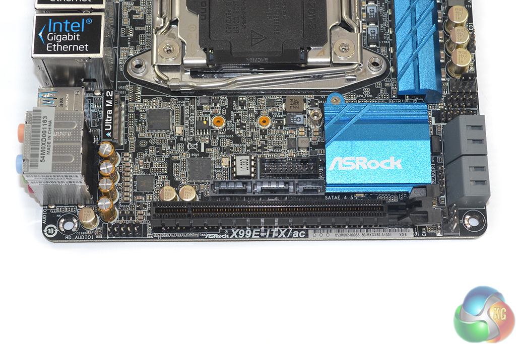
The solitary PCIe expansion slot is fed by sixteen Gen 3 lanes from the LGA 2011-3 CPU. Given the HEDT platform's lack of integrated graphics, the vast majority of users will be installing a graphics card in this slot, unless the motherboard is used for a remotely-accessed machine.
Directly above the PCIe x16 slot is the motherboard's SATA-Express connector. Its positioning will force a user to destroy their cable management efforts if they use the 10Gbps, chipset-fed connector or the pair of SATA 6Gbps ports. However, in many SFF builds, where multiple drives are required in a tight space, cable management proficiency may not be of great concern.
Above the SATA-Express connector is the motherboard's chipset-fed USB 3.0 header. Its positioning makes cable management a challenge for users who are trying to build an eye-candy mini-ITX system. This port can be converted to provide a second USB 2.0 header by using ASRock's bundled adapter. Next to the USB 3.0 header is the single socketed BIOS chip.
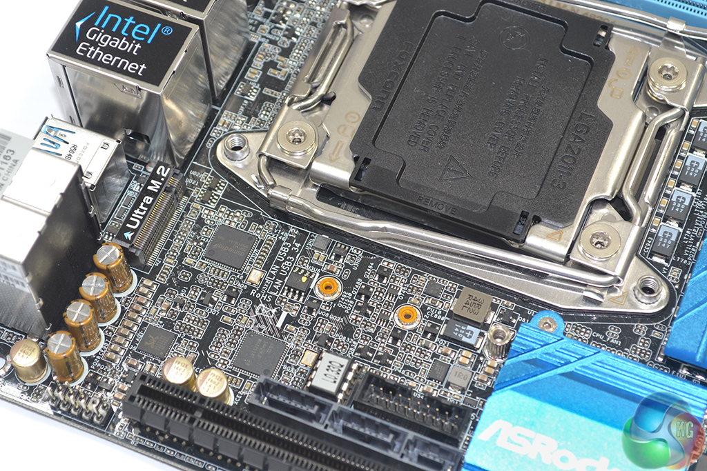
ASRock's Ultra M.2 connector can provide up to 32Gbps of bandwidth by way of four PCIe 3.0 lanes from the CPU. Alternatively, a SATA-fed M.2 drive can be installed in the slot. ASRock provides mounting positions for 42-, 60-, and 80-mm long M.2 devices.
I would have liked to see another M.2 slot on this motherboard. I know that sounds like harsh feedback for a mITX offering that crams so much hardware in so little space, but ASRock has plenty of CPU PCIe lanes and chipset SATA connections spare.
The additional connector may have been able to mount its drive over the existing slot, on the motherboard's rear, or even vertically. This would provide extra flexibility for high-speed or cable-free storage.
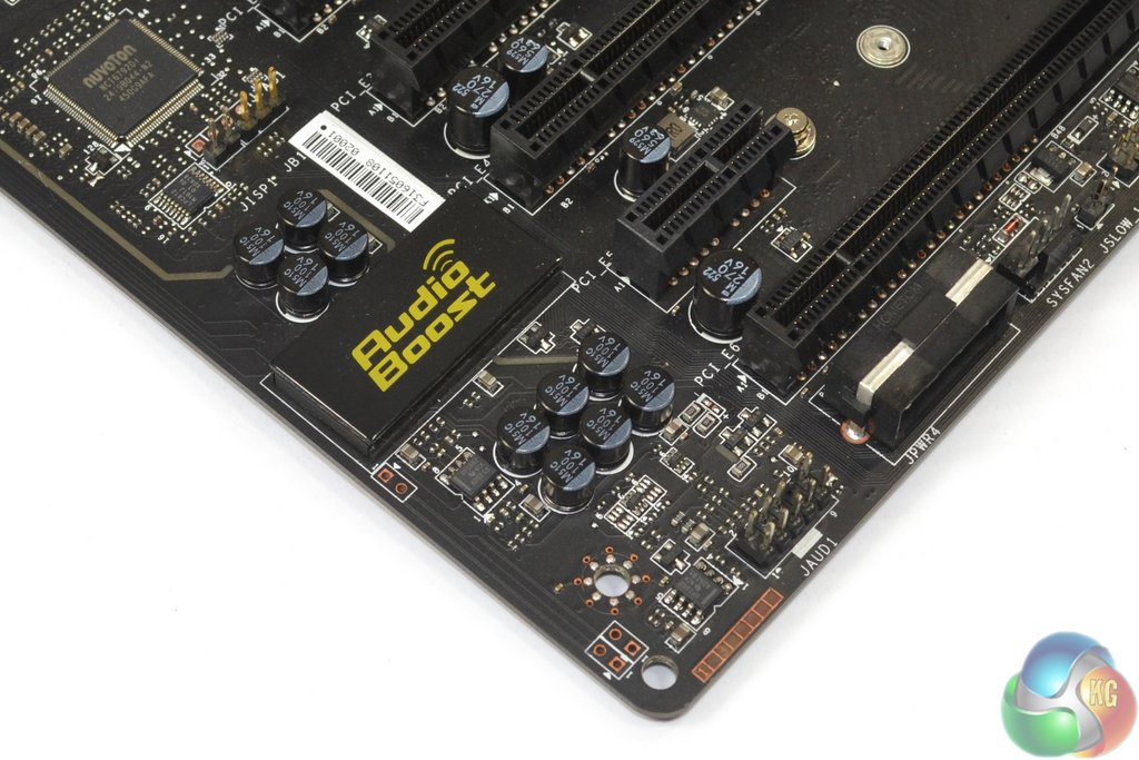
Audio hardware consists of Realtek's popular ALC 1150 codec in an unshielded mount, a Texas Instruments NE5532 operational amplifier, and four dedicated Nichicon Fine Gold audio capacitors.
The system is similar to ASRock's and competing vendors' offerings on other X99 motherboards, however it does cut the capacitor count. Minimising path length, the front panel audio connector is directly beneath Nichicon's capacitors.
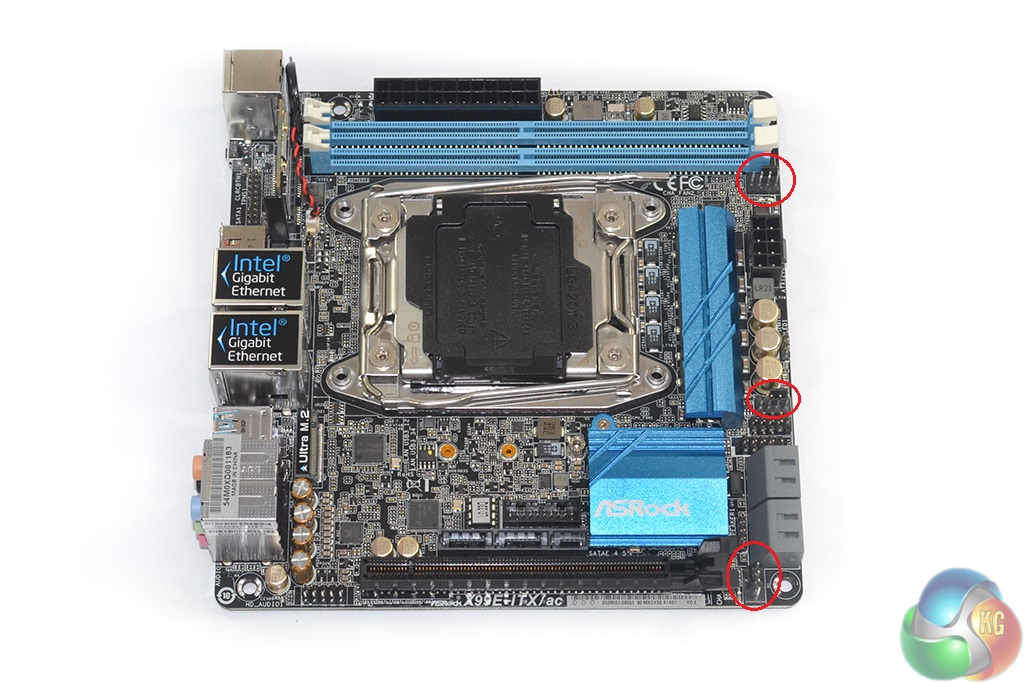
All three 4-pin fan headers reside along the X99E-ITX/ac motherboard's right edge. One header is allocated CPU fan duties while the others are controlled as chassis fans. Thanks to the rear-mounted Nuvoton NCT6791D chipset, all headers are given precise control and monitoring capability through ASRock's UEFI and OS utility.
Screw heads on the motherboard's rear side show that the chipset and VRM heatsinks are easy to remove. Perhaps a watercooling manufacturer will lock on to this point and provide a full-cover waterblock for the motherboard, CPU, and VRM. We have seen Bitspower offer such a contraption for Asus' mITX Maximus motherboards.
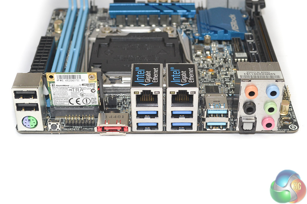
The healthy set of rear IO ports consists of:
- 2x USB 2.0
- 1x PS/2
- 1x Clear CMOS button
- 1x eSATA 6Gbps connector (from the X99 chipset)
- 2x Intel GbE NICs (I218-V and I211-AT)
- 4x USB 3.0 (from the X99 chipset)
- 2x USB 3.1 Type-A (from an ASMedia ASM1142 PCIe 2.0 x2 chipset)
- 1x Optical SPDIF output
- Audio jacks
Star of the rear IO show is the pair of USB 3.1 Type-A ports which are differentiated by their aqua blue colouring. These are provided via ASMedia's ASM1142 controller and support up to 10Gbps transfer rates. They will not support the enhanced power delivery capabilities that the USB 3.1 Type-C implementation can theoretically provide.
The pair of Intel NICs support teaming which could make them potentially useful to users wanting to build a network-based workstation.
ASRock leaves a gap above the eSATA connector so that the WiFi aerial ports can be screwed into the rear IO shield.
41$/hour@kitguru
>/